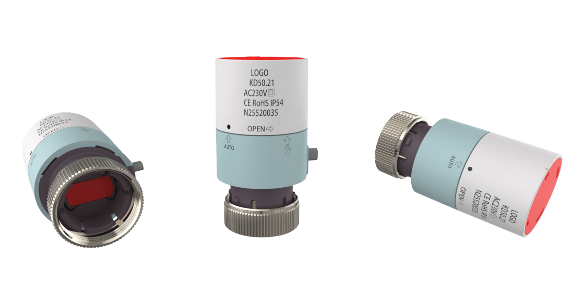
A thermo-electric actuator is a reliable drive unit designed for HVAC control valves and underfloor heating manifolds. It's built on the thermal actuator and utilizes the thermal expansion of wax to turn on or off the hot water flow in a zone automatically.
Water circulation control systems equipped with thermo-electric actuators offer outstanding advantages: low power consumption, zero operating noise, maintenance-free operation, no water hammer, automatic closing upon power-off, and easy installation and commissioning — making them the ideal solution for HVAC water loop control.
As one of the leading thermal actuator manufacturers in the industry, we builds our OEM thermo-electric actuators from our own self-produced Wax Thermostatic Elements — the heart of every actuator.
By controlling the core technology in-house, we ensure:
Stable and consistent performance across every batch.
Faster delivery and competitive pricing, with no dependence on third-party suppliers.
Proven reliability, backed by millions of thermal actuators supplied to global HVAC brands.
We offer a wide range of OEM and ODM customization options to meet your specific requirements, including but not limited to:
Product Logo, markings, labels, and packaging – customize for brand identity and market needs.
Operating voltage options – choose from 24V, 110V, or 230V to fit your system.
Wire and cable length – default 80 cm, adjustable as required.
Valve closing position adaptation – default 10 mm, adjustable to suit different valve types.
Housing color and top cap design – tailor the appearance to match your brand.
Our flexible customization ensures that every actuator can be perfectly adapted to your product design and application needs.
This OEM thermoelectric actuator uses our thermal actuator and operates based on the expansion and contraction of temperature-sensitive wax.
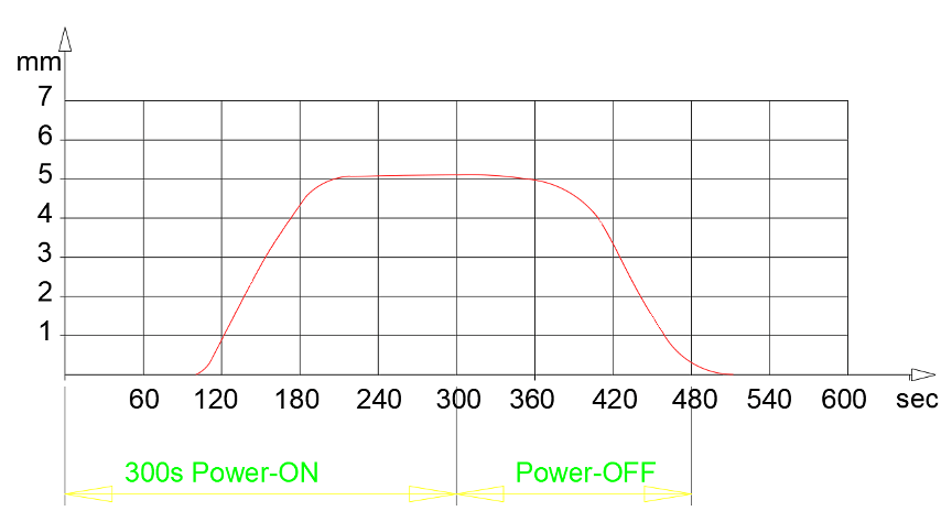
It is used to automatically controls fluid flow. When it is powered on, the PTC heating element inside the thermal actuator generates heat. This heat causes the temperature-sensitive wax to melt and expand in volume, pushing the piston outward. The outward movement of the piston drives the actuator mechanism upward, which in turn opens the valve. (See animation below)

When the power is turned off, the wax gradually cools and contracts, allowing the thermoelectric actuator to return to its original position. As a result, the valve stem closes automatically.
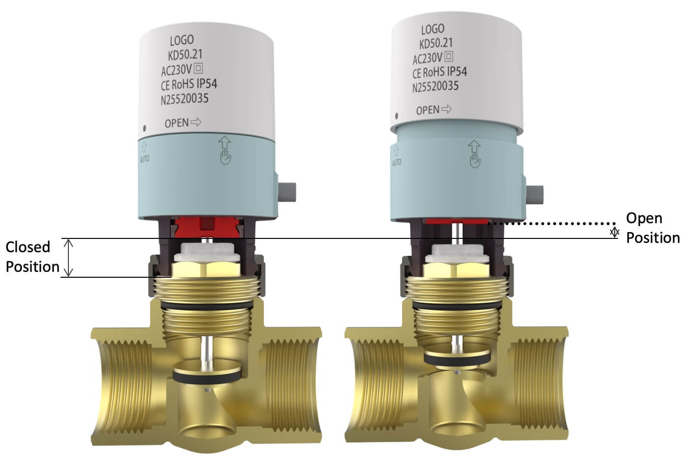
Perfect valve compatibility with no idle travel.
We can factory-adjust the actuator’s closing height to match various valves, ensuring maximum flow and reliable shut-off.
First-Open function with operation status indication.
The actuator automatically resets to automatic mode after power-on, reducing installation time and simplifying system commissioning.
Low power consumption.
Steady operation requires only about 1W, providing up to 50% energy savings compared to conventional actuators.
Waterproof protection design.
This thermo-electric actuator features internal O-rings and potting measures to ensure both waterproofing and electrical insulation. It operates reliably even when installed upside down.

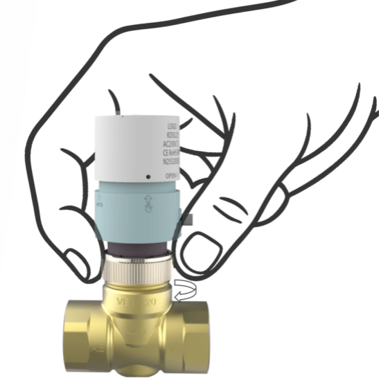
The OEM thermo-electric actuators we're offering feature two operating modes — Manual Open and Automatic — designed for flexibility and ease of installation.
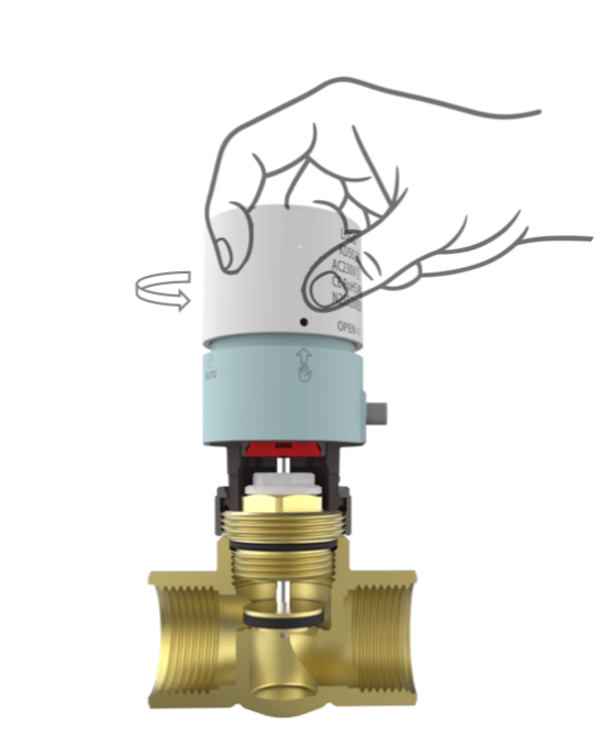
When power is off, the actuator can be manually switched to the open position.
• Rotate the actuator cap counterclockwise until the manual arrow aligns with the black dot — this indicates the valve is fully open and water flow is unblocked.
• To reset manually, simply rotate the cap clockwise to the “AUTO” position.
This function is especially useful during system commissioning or pressure testing, allowing easy valve operation without connecting power.
In automatic mode, the actuator responds to the thermostat’s signal:
• When powered on, it slowly opens the valve, and the rising cap indicates the open position.
• Power off automatically closes the valve.

If the actuator remains in Manual Open Mode, it will automatically reset to “AUTO” mode within about 2 minutes after power is applied — ensuring the system always returns to normal automatic operation.
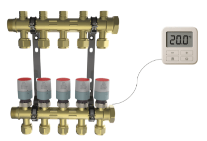
The thermo-electric actuator can be easily mounted on zone valves, radiator thermostatic valves, control valves, or underfloor heating manifolds.
Manually rotate the top cap to switch the actuator to the manual open position.
Tighten the bottom M30 nut clockwise by hand to securely connect it to the valve.
Ensure the thermostat is powered off before wiring. The actuator has no polarity requirements.
• The thermostat’s output current must be higher than the actuator’s inrush current at startup.
• If one thermostat controls multiple actuators, the total maximum inrush current must be considered.
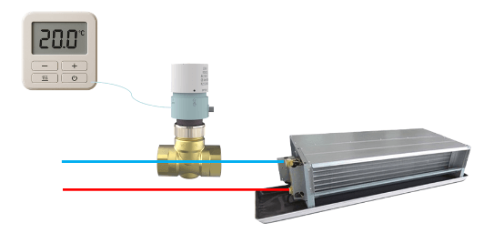
Thermo-electric Actuator installed on fan coil units to automatically regulate water flow.
System Recommendations
• It is recommended to install the thermo-electric actuator on the return line of the valve.
• For high-pressure systems, include a bypass valve to prevent tight shut-off issues and reduce noise caused by excessive differential pressure.